Huge progress on the robot and treat dispenser! They are connected and working together! Thanks to a very helpful suggestion from my wife I was able to implement a simple fix for the clogging problem. I cut some thin flexible plastic from the top of a takeout sushi container and cut one end into fingers. I attached it so that it reaches about one “treat height” above the belt. The fingers brush back extra treats that would get carried forward as a stack due to their stickiness but they don’t allow them to get jammed by the fingers because they are so weak and flexible. You can just see the fingers in this picture:

Detail of anti-clogging solution…
The fingers also make the kicker servo and armature more effective. I added a zip tie around the kicker servo to make it more stable and to transfer more of the energy to the treats. This works good and having run multiple full hopper tests I can confirm that it successfully clears all the treats without jamming.
The next thing I needed to do was to mount the dispenser on the robot and as part of that mount the servo controller and the servo batteries somewhere. I got some nice 1.5cm x 4mm standoffs and drilled and countersunk some holes in the treat dispenser base plate and mounted the controller behind the left side servo. I was able to cut a couple of slots and mount the battery pack using a velcro strap next to the controller.

Controller board mounted using standoffs and the battery pack for the servos mounted using velcro strap.
Two new tools made a huge difference in this process, I got a set of small metric wrenches and a set of coarse and fine files. The wrenches allow the tightening of these tiny fasteners so much better and more easily and the files allowed me to drill out the slots and then remove the rest of the material by filing to create nice clean slots without cracking/burning/destroying the acrylic.

File set, not an expensive one but it works great, the small files on the right are perfect for making slots or fitted holes in acrylic. Just use the brush regularly to clear the file when working with plastic. Also, go slow to not melt the plastic with friction.

Tiny wrenches apparently usually used for working on carburetors. The metric ones are wonderful for tightening the tiny nuts on the robot without mangling them.
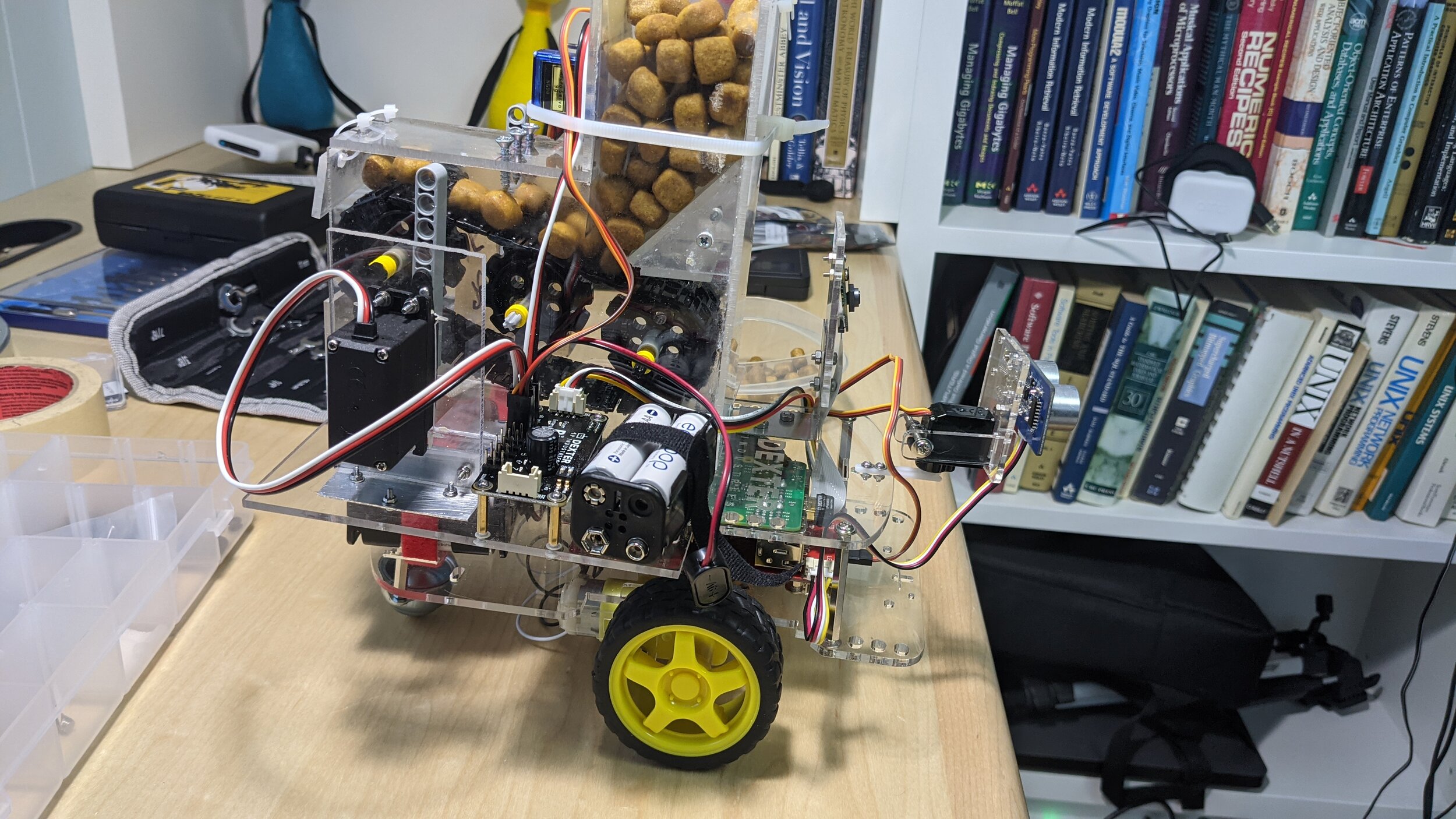
I was able to use some of the existing holes in the upper deck of the GoPiGo robot to finally mount the treat dispenser on top of it just behind the camera. Handily it also centers most of the weight of the treat dispenser over the drive axles and it doesn’t seem to make the robot more prone to tipping. I was worried because this particular robot only has a single roller caster in the back.

Using the existing holes in the upper deck of the GoPiGo robot to mount the treat dispenser.
I ran a test with everything integrated this morning and the robot was able to move, turn, use it’s sensors and dispense treats with no problems. Here is the video of the run:
I’m really happy with the progress so far, the next step is to make the software part of this project more usable. After messing around with trying to make the robot autonomous I have decided that it just isn’t up to it in terms of sensors, steering and maneuverability. So, I’m going to implement a dashboard and keyboard controls so I can directly control the robot and treat dispenser remotely via an ssh tunnel.


