I took a couple of weeks off after my last project to catch up on my comic book reading. I can report that I got through my entire TBR pile, quite satisfying. I also started working on designs for a couple of future projects, went for some walks, did some cooking and took some naps. At the end of my “vacation” I needed something small to do in the shop that would be fun and not require new materials or a lot of time commitment.
I pulled out my Build Dice from Simone Yetch’s online store, the idea is you roll the three dice and they suggest a thing to build. So, I rolled the following:
This was pretty good for a first roll, usually I have to roll a few times to get something that is interesting to me. I have been wanting to do something with 1/8” veneers, triangles, and scrap wood so this was the perfect excuse.
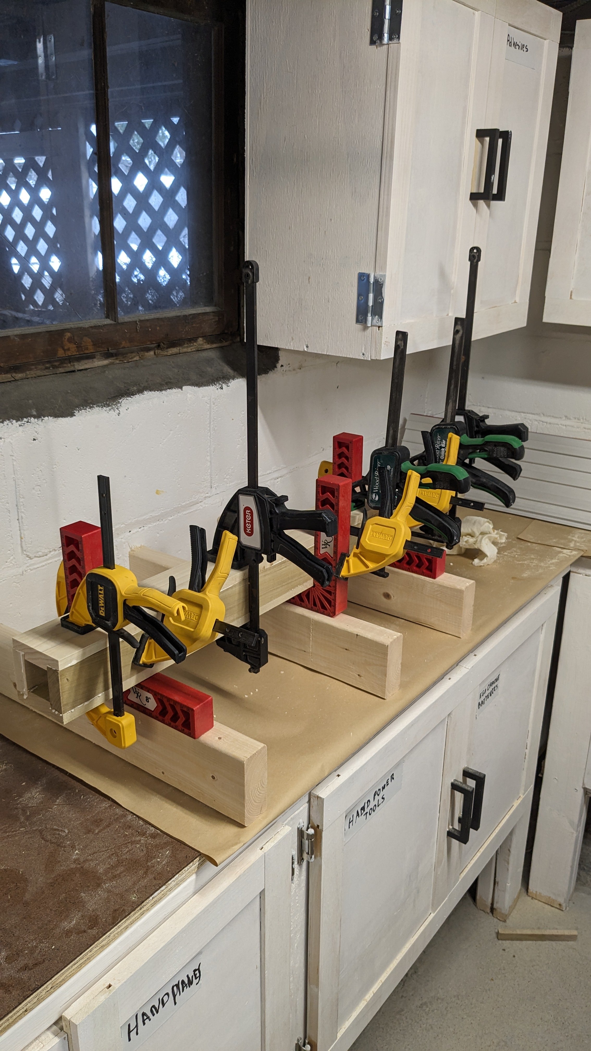
I had a nice glue-up that I didn’t use from another project that was 2” thick and was a sandwich of 1/4” walnut on both sides and 1 1/2” maple in the middle. That set the size of the slices I was going to use to 2” and therefore the size of the triangles.
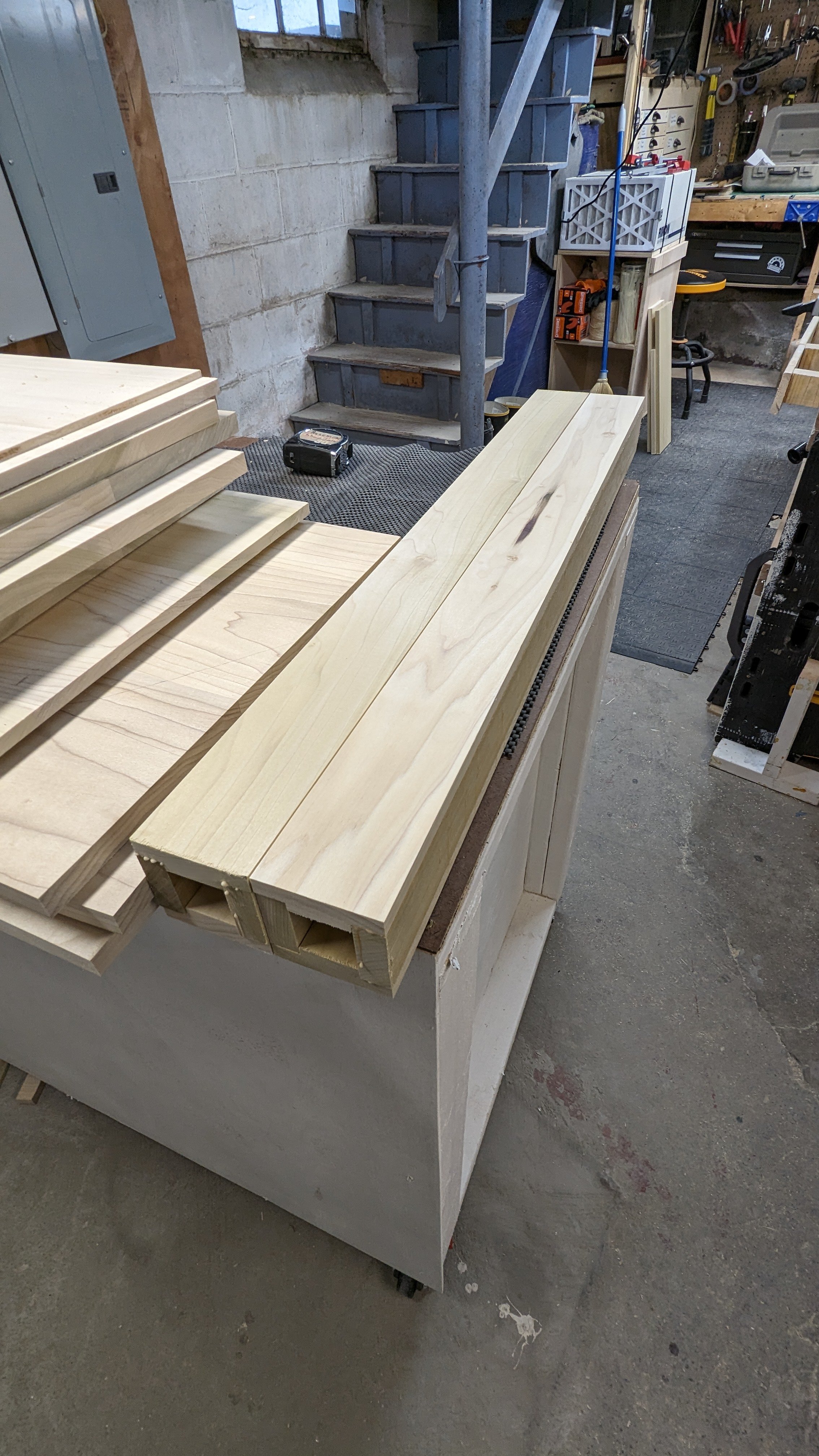
I had some walnut off cuts and also western red cedar off cuts which I cut to 2” and I cut 1/8” thick slices out of all of them. They weren’t super even but I was figuring I’d have to flatten everything later.
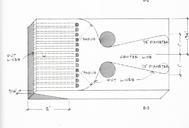
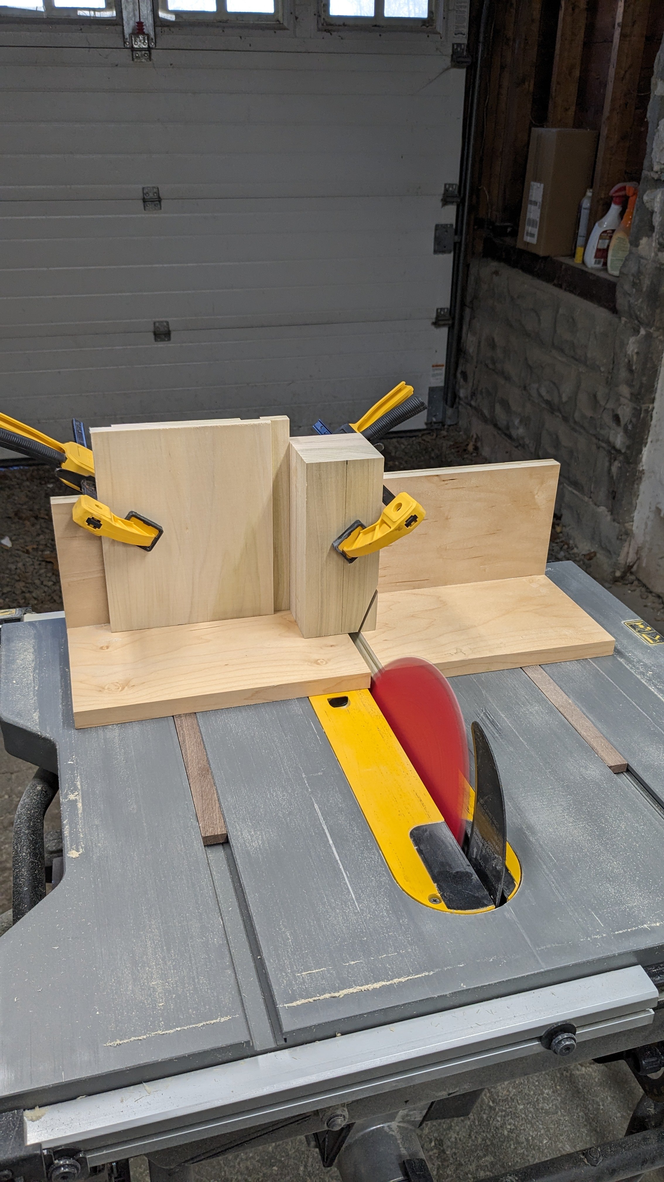
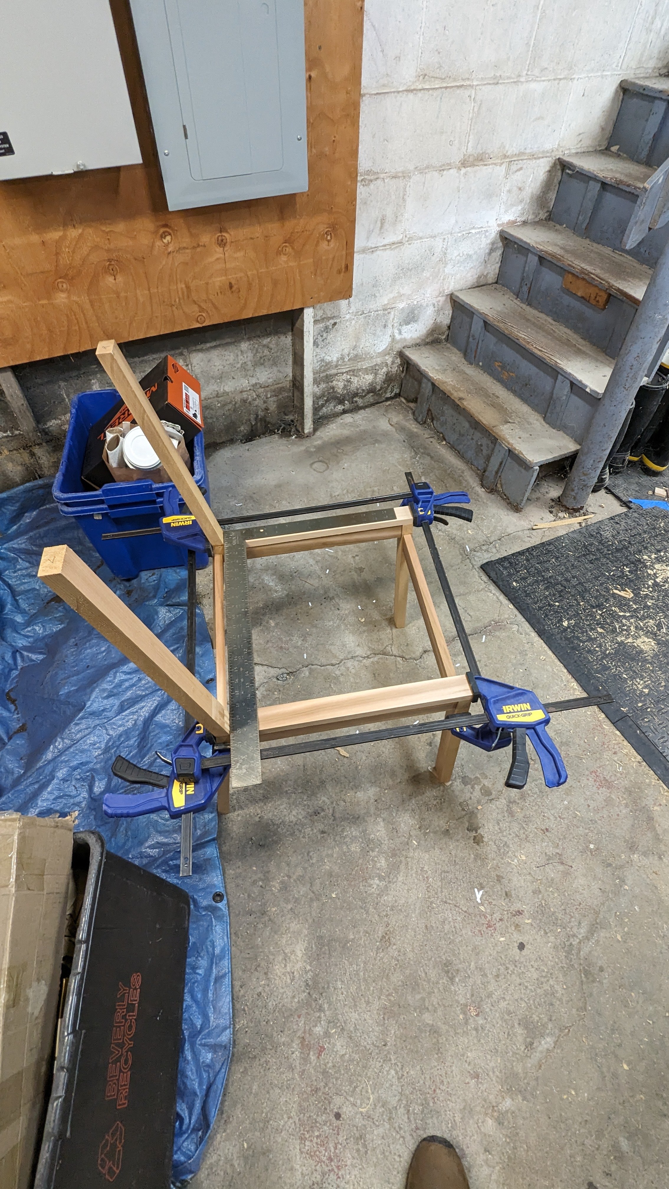
I built a small cross cut sled for my table saw and put a stop on it at the right angle to cut my triangles.
I cut a whole bunch of triangles from the 1/8” x 2” strips, it went very quickly using the sled. I deliberately didn’t make a plan for how many of each or a particular pattern I wanted to do. I just got a 12” x 15” piece of 1/2” plywood that was pretty flat and marked a center line on it and started putting triangles on it until I saw the pattern that I wanted.

It was a pure accident that I was able to make a border around the central pattern using the glue up triangles. I didn’t worry about perfect placement or alignment of the pieces, and I glued them down to the plywood. After the glue had cured I went back and filled all of the cracks with fine wood filler so that the surface would be consistent when I leveled it.
When the filler had hardened I got out my trusty Makita Belt Sander with a 60 grit belt and leveled the whole surface. I followed that up by sanding 80, 120, 220, and finally 320 grit to get a nice smooth surface.
In the spirit of using up things that were “trash” I had a can of Cherry Danish Oil which after testing I found to be way too red for the project I bought it for and in general probably too red for me. I thought red would be a cool color for this mixture of woods to bring out different tones and features and add a bit of surprise to the look. So I applied the danish oil and I also wet sanded the first coat to see if I could get some grain filling with different colors from all the wood.
I really liked the results, the “dirty” look to the maple is a really cool effect. Finally I had some 1”x1” maple offcut that I made a frame from to set off the panel. I just sanded the frame nicely and put paste wax on it. It was a two day project, but I like how it came up and now I have some art for the shop wall.