Building Project: Shop Expansion

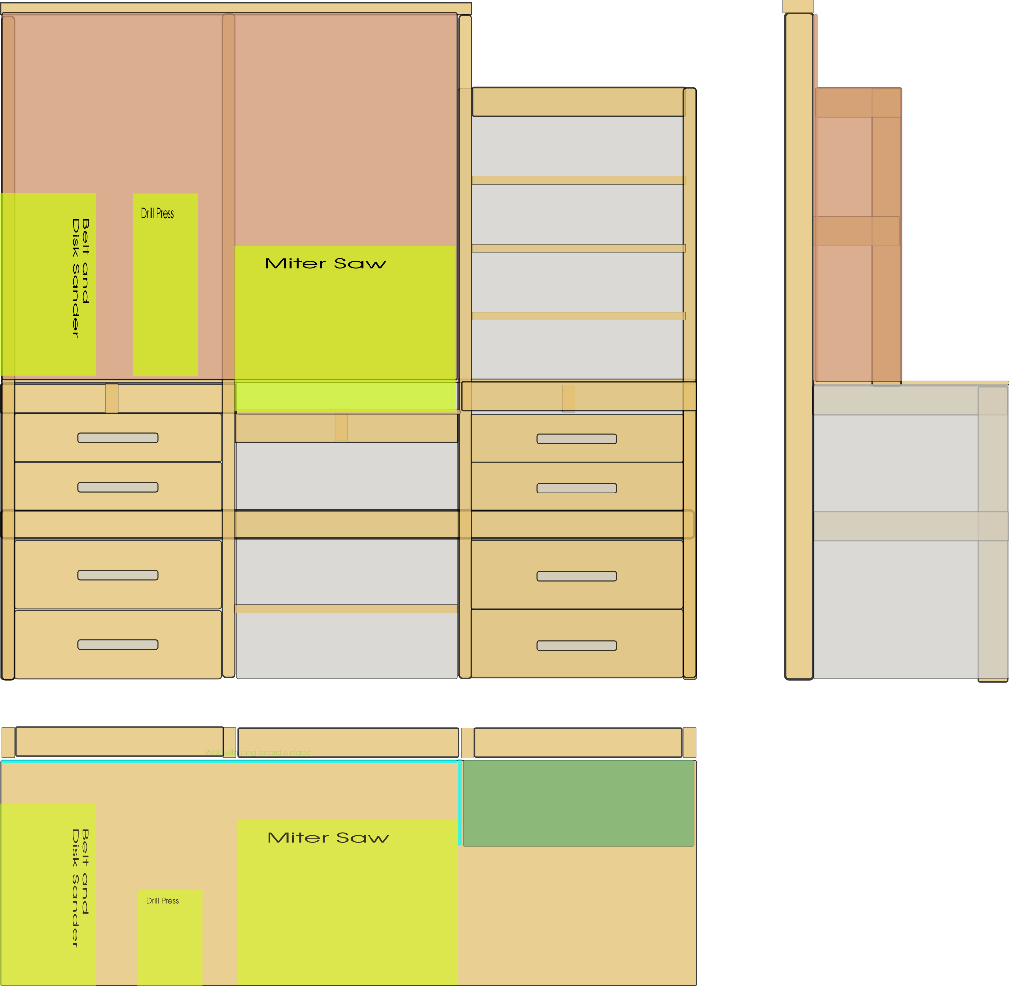
As I mentioned in my previous post I have a furniture project coming up to build a custom convertible sofa bed for our library/guest room. Before that I needed to add some new tools to my shop and give them someplace to live. One important feature is a sliding compound power miter saw station where the front of the bench provides the infeed/outfeed support for the miter saw. The bench will also have a ruler and an adjustable stop for the infeed of the miter saw. Because I was going to build new benches and such I also decided to add more storage. The storage is drawers, shelves, and pegboard to give everything I have a place to live, plus some extra capacity. I’ve never built or installed drawers before so this was also a skills upgrade. See the design drawing below for an idea of what I was shooting for…

Side, top, and front views of new bench design…

The first challenge was ordering all the stock and hardware for the new bench. I had two problems with my order. One was self-inflicted, I ordered the wrong length 2x4s due to clicking on an adjacent item in the online ordering system. The second one was the store’s problem, they omitted half my plywood and that was after a one day delay. The good news is that now I can go in person to the store and so I went and picked up the missing plywood and a bunch of additional 2x4s.

Some of my order…

Some of my order…

I set up a temporary miter saw station and my new table saw in the garage which is attached to the shop. This is probably where the table saw will always be used just for space reasons. I got a folding and roll away table saw so it can be out of the way when I’m not using it. Also, the car needs to go in the garage most of the time.

Temporary miter station and table saw station in the garage

Temporary miter station and table saw station in the garage

The first part of the build was to build the frame of the bench. I actually built it as three independent units and then connected them. Note the lowered section in the middle to allow the deck of the miter saw to line up with the surface of the bench. The miter saw made all the repeated cuts so easy and quick. Also it makes perfect consistent square cuts where I would probably have some “variation” using a hand held circular saw.

One unit of three…

One unit of three…

Three units framed and connected… ooh and my first drawer…

Three units framed and connected… ooh and my first drawer…

You can see my very first drawer in the image above. It was so cool to have a table saw and be able to rip all the sanded maple 1/2” plywood to the right dimension and then to length on the miter saw. I also made the dado in the drawer sides using the table saw, just putting each piece of stock through with the blade set to about 1/4” height and shifting it 1/16” for three passes. I was able to cut the drawer bottoms by just ripping the panels to the right width ( the inside width of the drawer plus 3/8” so it sits inside the dado). I used a very simple butt joint with glue and pre-drilled countersunk 1” screws. The drawer slides are nice 24” full extension slides so it’s easy to get to everything in the drawers. I intentionally set them back from the front of the unit so that there are still clamping surfaces and to protect them from getting sawdust and such into them. You can also see the bench tops which are two layers of 1/2 plywood.

All the drawers installed and the miter saw in it’s new home…

All the drawers installed and the miter saw in it’s new home…

The next part was to add the pegboard on 2/3 of the bench to hang up tools and some shelves on the last 1/3 of the bench to have some open shelf storage. There is also a shelf under the miter saw as well and floor storage under that. I also installed and set up the other tools: drill press and sanding station.

All the tools installed on the bench top, pegboard and shelves as well…

All the tools installed on the bench top, pegboard and shelves as well…

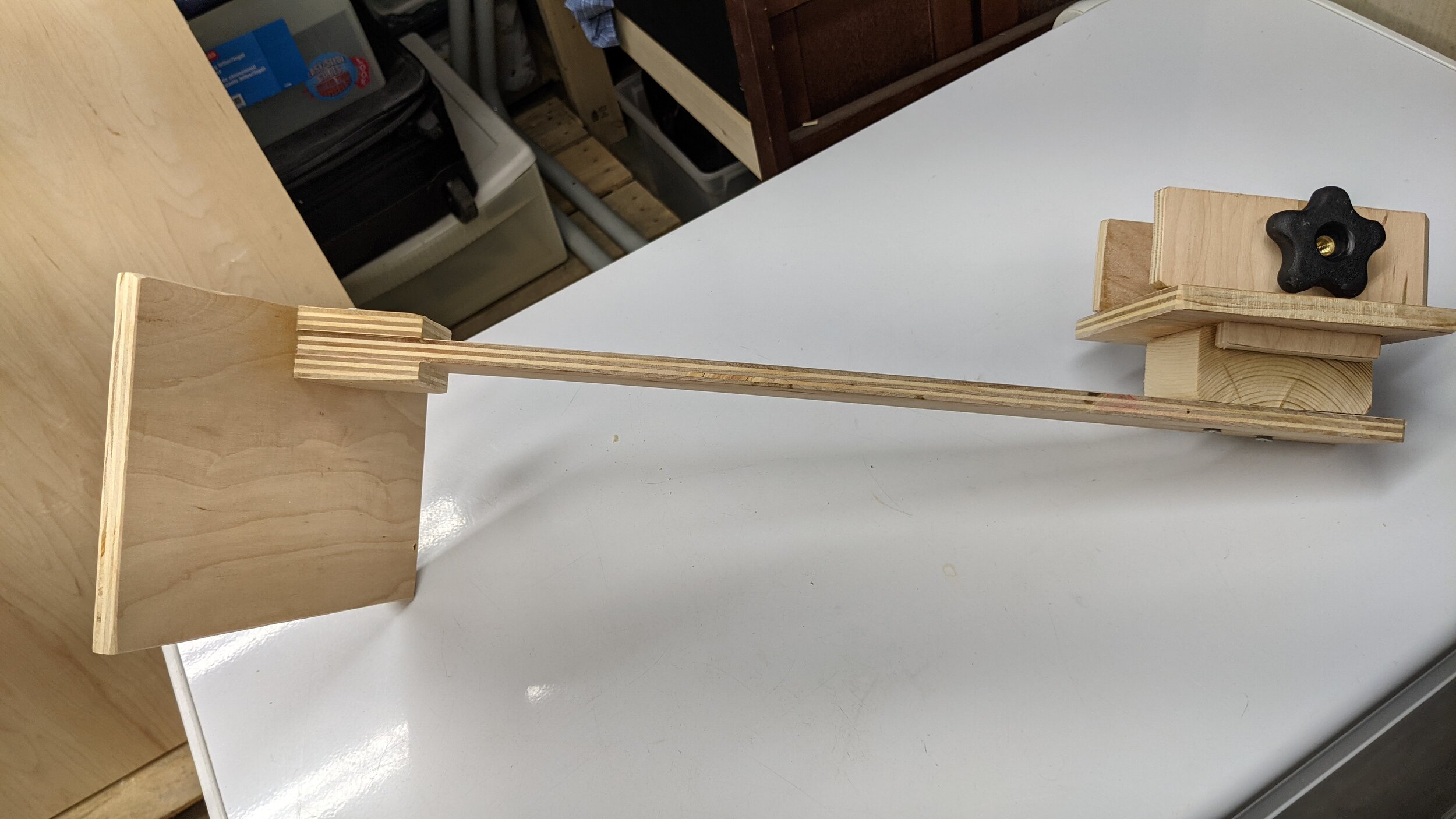
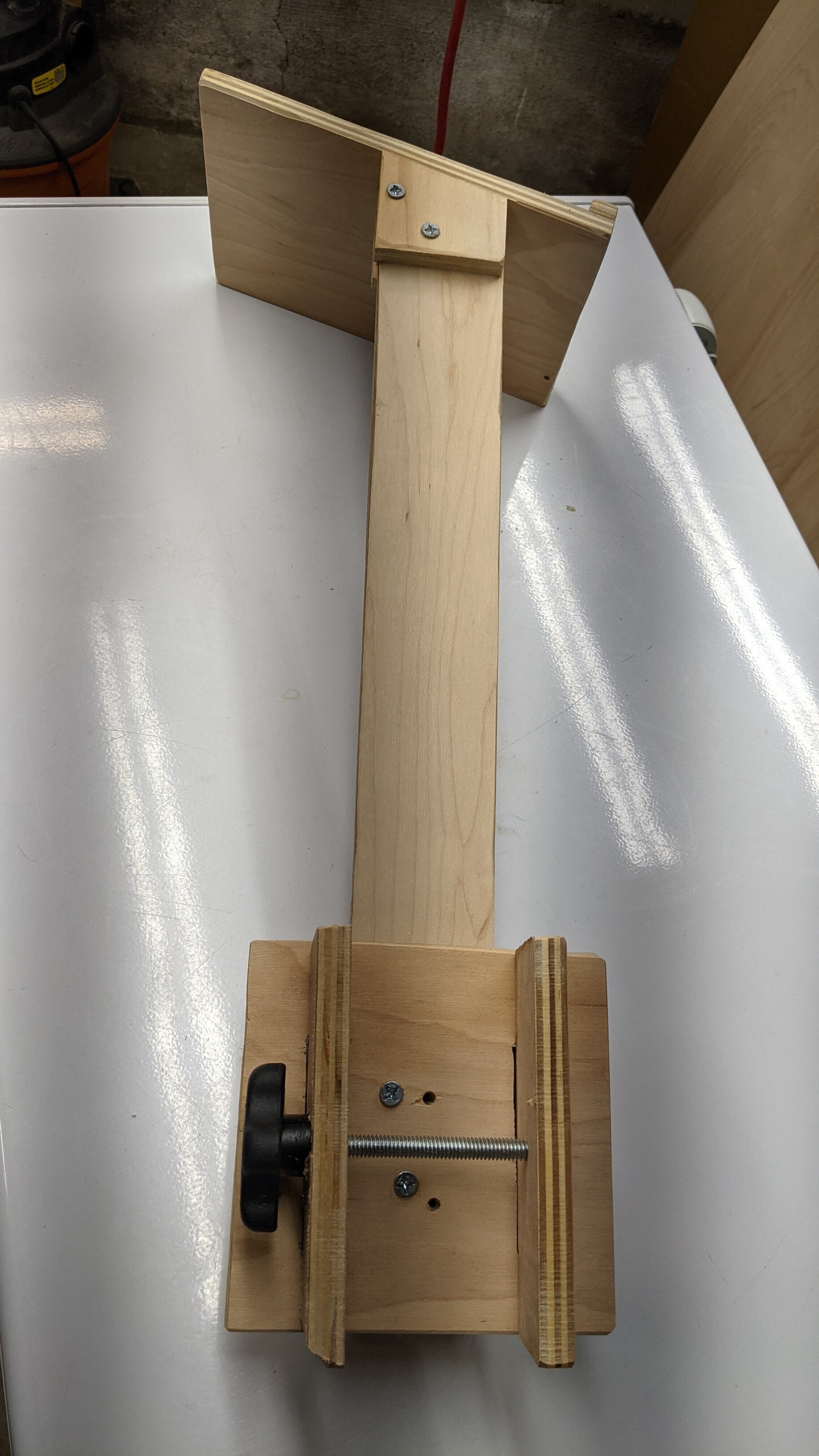
After putting stuff in the drawers and hanging up a bunch of tools, I installed the miter saw adjustable stop and ruler. I built a jig for my router and carefully routed a channel to install it after doing some work to level/flatten the infeed side of the bench. The stop came out great and it largely removes the need to measure and mark when I’m cutting multiple pieces.

Miter saw stop and ruler…

Miter saw stop and ruler…

So that’s the whole saga… It took about five days or so end to end and I think it is a good representation of my original design. I’m very happy with the functionality, the machines, and the storage. I’m reviewing my design for the bed project and I’ll probably get started on that in a week or so.

Miscellaneous projects...

I’m about to start a new construction project and it reminded me that I’ve done a few random projects and not posted about them at all… So, here’s a rundown of the small stuff…

Fixed the dimmer that didn’t work well for 20+ years…

In our dining room there was a weird dimmer switch that had a touch plate that was supposed to adjust by sliding your finger on it or something. It didn’t work right for two reasons. First, if you tapped it it was supposed to just turn on the light, it would often fail at this or leave the light flickering on and off. Second, I could find no reliable way to control the dimming with it, it either went full on suddenly or off to flickering… We lived with it since we moved into the house and I kept meaning to have and electrician replace it. Finally I got the courage together to replace the damn thing. It was actually very easy and the instructions for the new dimmer were very clear. The new dimmer is the proper rating for the LED lights in the fixture and had a normal on-off switch and slider for dimming. The hardest part was finding the circuit that this light was on, it wasn’t on anything labeled in our box as “dining room” and turned out to be on the circuit with the basement and some of the outlets in the kitchen ( wtf? ).

A normal functioning dimmer for the dining room…

A normal functioning dimmer for the dining room…

Fix the split in the front foyer door

Our front foyer door developed a split in the wood near the door knob a few ( 10, 15, who knows… ) years ago. And I attempted to glue it in the past and failed and had since just had some masking tape over it to prevent it catching on things. Don’t judge me. Recently, I cut out the damaged wood, made a patch and glued and fastened the patch in place with brads and sanded it flush with the original door. I even painted it to mostly match.
PXL_20210616_124547453.jpg

Got the paper towel off the counter

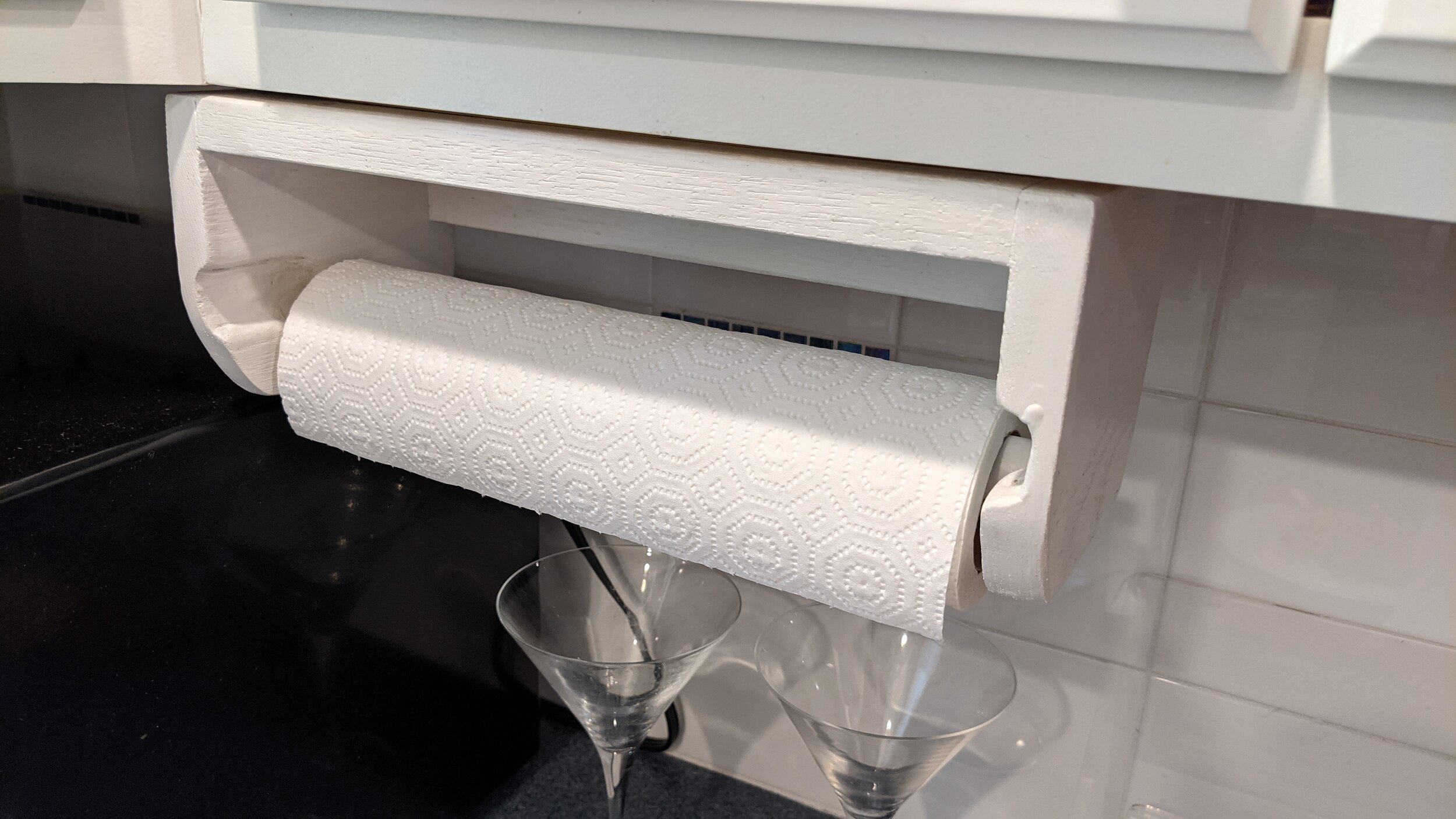
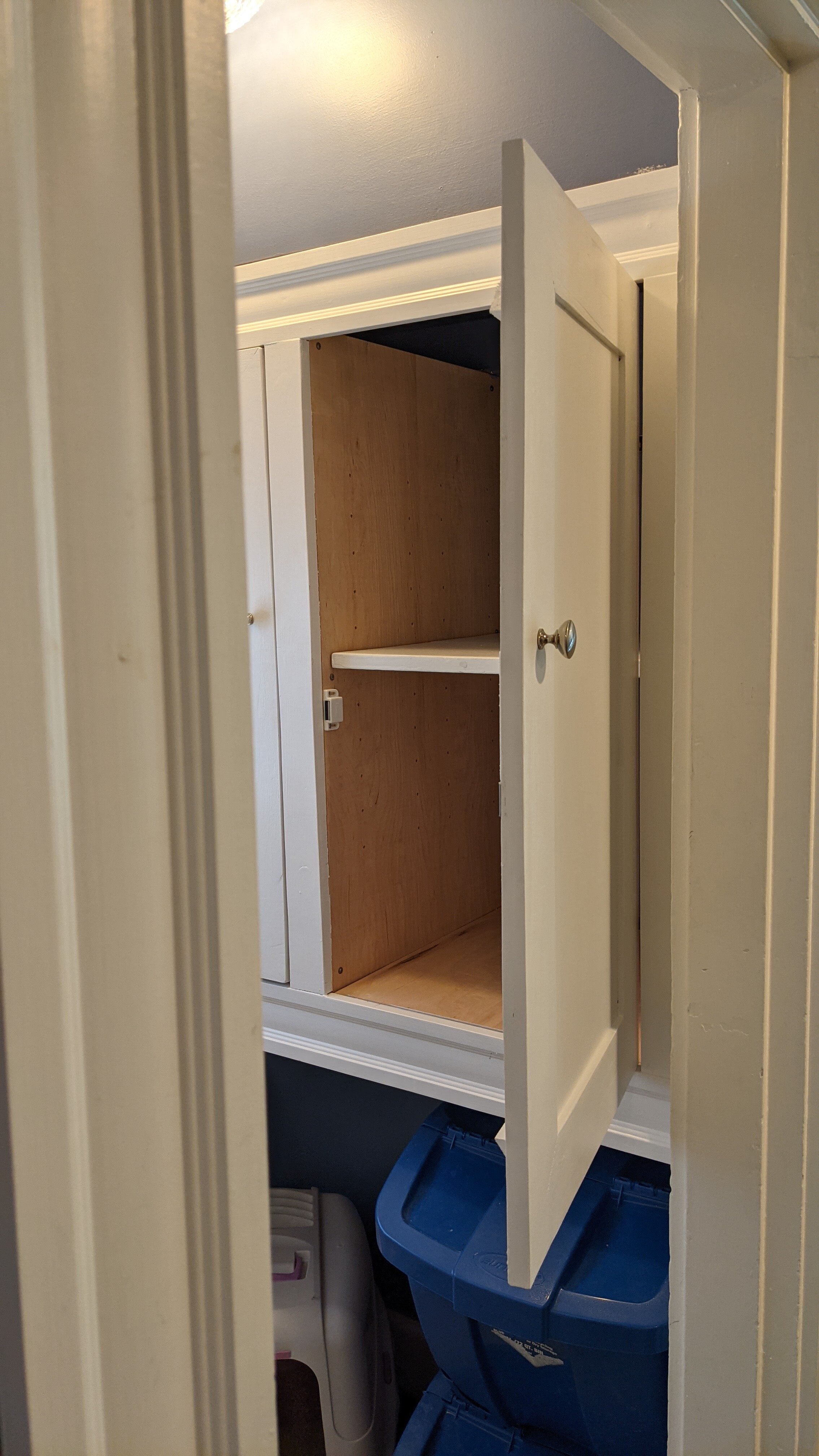
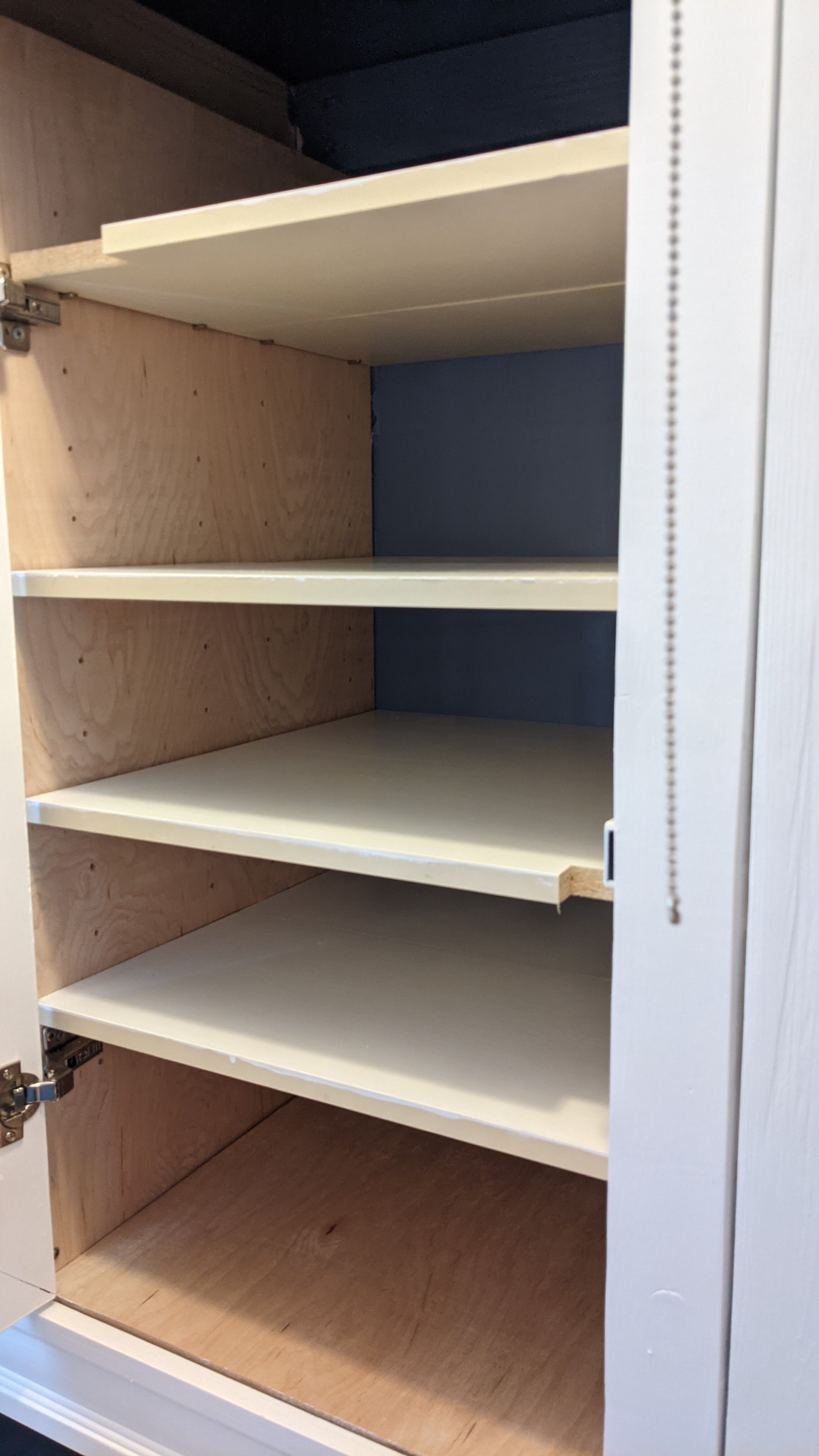
For a couple of decades our paper towel in the kitchen has been on a vertical dispenser on the counter. I’ve always regretted that dispenser since it was always in the way or behind something. Also, it would move when you tried to pull paper towel off of it. I built a dispenser that could mount to the underside of the cabinet to solve this problem. It is better ( not perfect ) for one handed use, and it solves all the other problems. I used some old book shelf material I had in the scrap pile to build it and I painted it to match the cabinets.
PXL_20210616_124636446.jpg

Converted Dana’s bike to grip shift

Even after the complete overhaul and rebuild last year, the shifters on Dana’s bike weren’t working correctly and they were making it hard for her to ride. I got some off the shelf grip shifters and replacement brake levers and replaced the original Shimano stuff. They work great and I was also able to adjust the pull on the brakes to make them a lot more aggressive. The shifters work with any Shimano drivetrain as long as it is a 3x7 setup. I also finally understood derailleur adjustment and was able to dial in the shifting. I got these cool purple grips as well that match the bike frame.

PXL_20210616_140803172.jpg

Converted all of the lights in the basement to LED from fluorescent and added a bunch

I have wanted to add more lighting to the basement ( where my workshop is ) and had been dreading trying to lure an electrician out here to do a small job. One day I noticed that there was an old dead fixture up in the joist bay and it was still wired in to the main light switch in the basement. I removed it and got rid of it and converted that wiring to be a switched outlet. I then got these cool four foot LED shop lights that can daisy chain. I was able to add a bunch of them with no issues. Now I can see what I’m doing in the workshop which is wonderful.

I also replaced the old fluorescent bulbs in the existing fixtures with LED conversion bulbs

I also replaced the old fluorescent bulbs in the existing fixtures with LED conversion bulbs

Next project, shop expansion to do the next next project

After the hall cabinet project I realized that I needed some additional tools to do nicer and more precise projects more easily. I said that I would wait until I came up with a plan for another “upstairs quality” project and then I would expand the shop to do that one. The next next project that came up was to build a custom folding bed/couch for the guest room/library upstairs. It will have a storage chest as the headboard to store bedding and other linens and such. I’ve got the design drawn up and it will allow us to move from a “full” size futon bed to a “queen” size bed in our library. This will be nice for guests and for us since sometimes when one of us has a cold we sleep in there to let the other one get some rest. I’m also going to build some storage into the base as well.

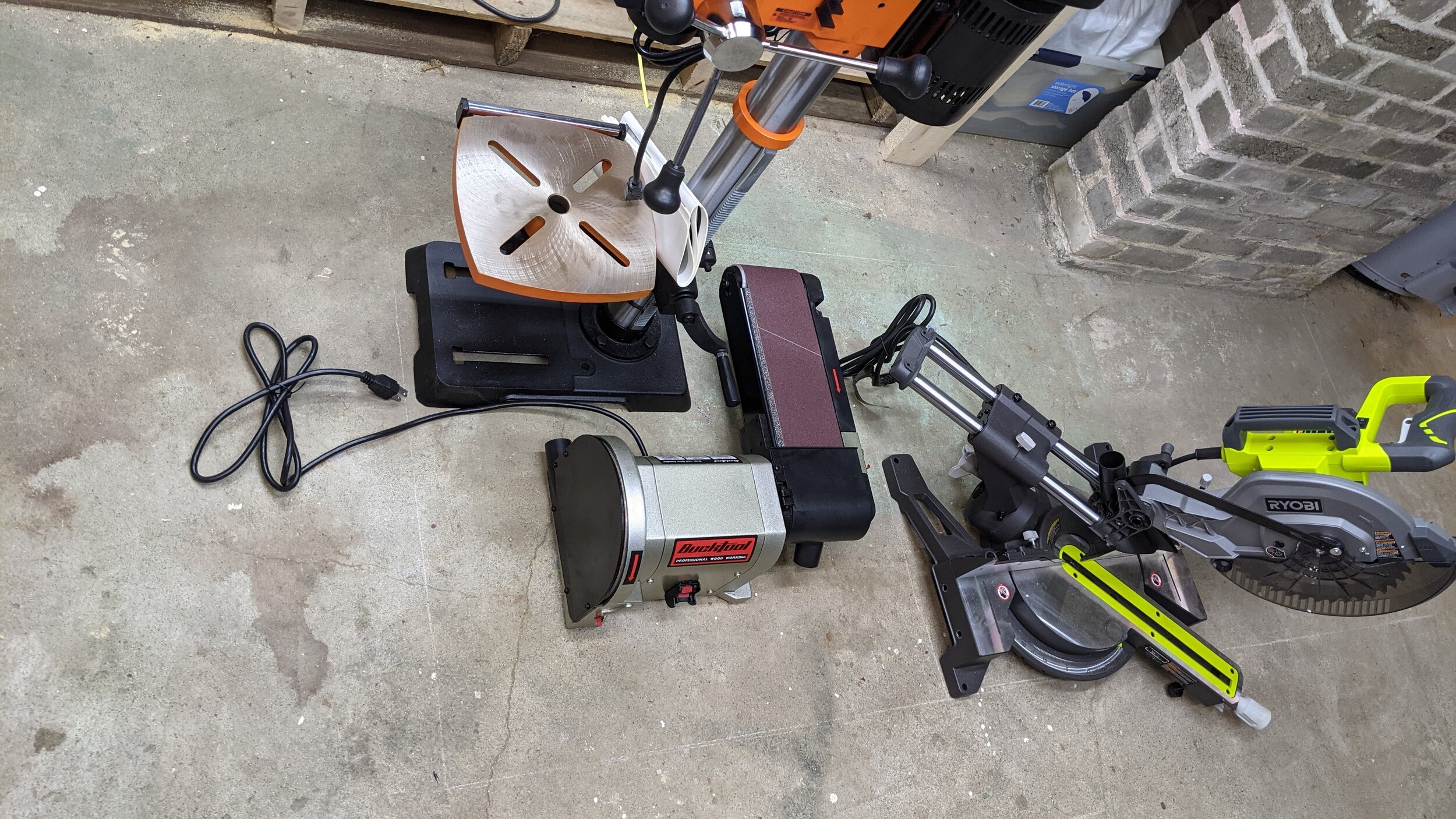
But first I need to expand the shop so I got a nice sliding compound miter saw, a table saw on a folding rolling stand, a drill press, and a belt and disk sanding station. I’m going to build a miter saw bench that will also support the drill press and sanding station. The table saw folds up and gets stored across the room and most likely used in my garage since it won’t be much use in my shop space.

Picture a bench under these tools with a pegboard behind them and eight drawers underneath them ( I really need the storage ) and a nice 30x30 work surface at the end. The front edge of the bench will be kept clear and the miter saw recessed so that it’s deck is flush with the bench top and thus will form the infeed and outfeed for the miter saw. I’m even going to put T-track into the bench top with a removable stop and an embedded ruler on the infeed side for quick measuring and repeated cuts.

Ok, that’s the update, I’ll post about the shop project soon… I’m waiting for materials to be delivered today!

Robot Project: Acrylic treat dispenser

Over the holidays, after evaluating alternatives for cutting the acrylic and aluminum, I got a bench top band saw.

processed_PXL_20201230_204526609.jpg

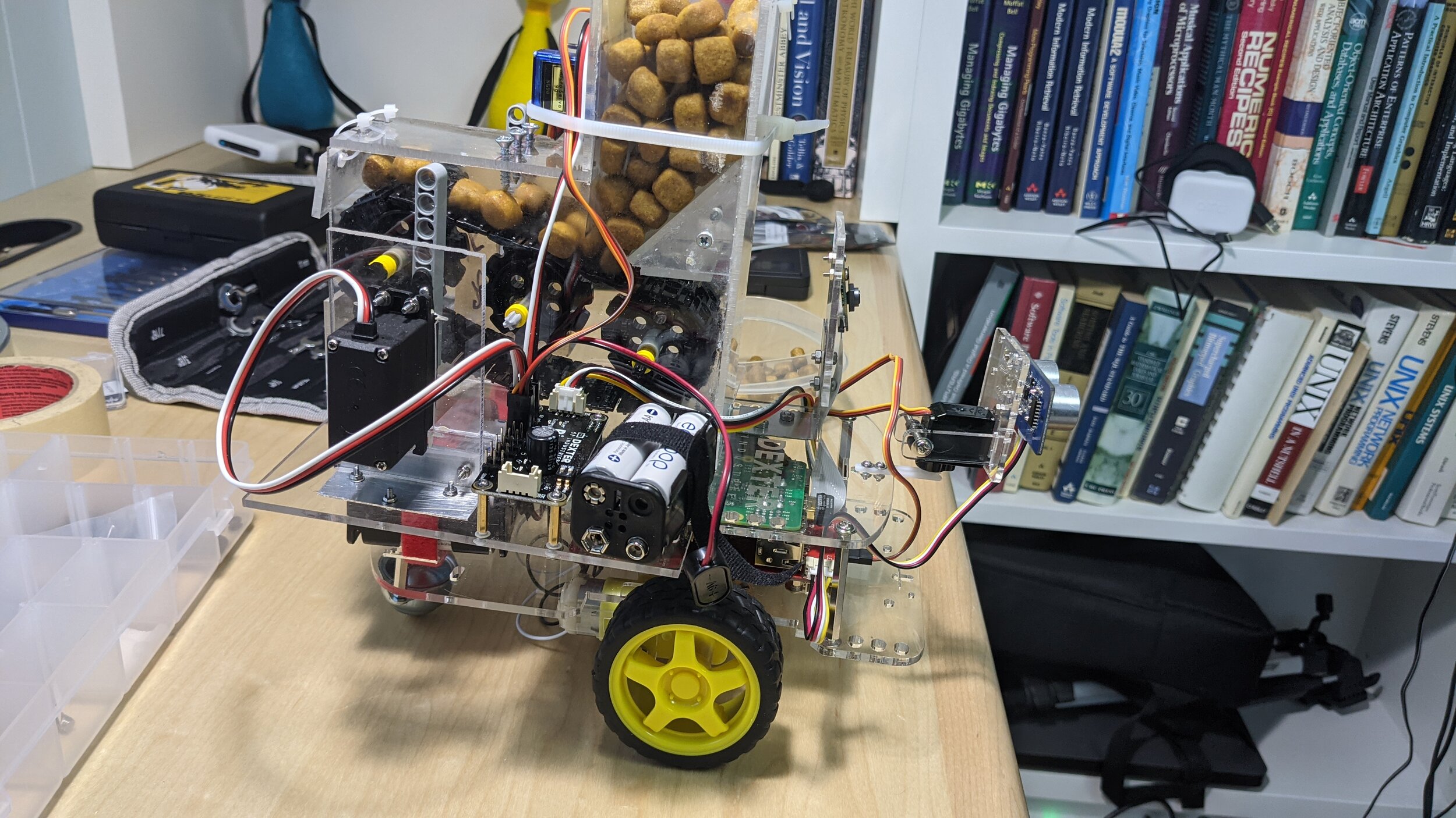
It has allowed me to make all the parts for the feeder quickly and reasonably straight. I even figured out how to make the treat ramp inside to keep them from getting stuck. I used CA glue to bond everything. That was a little learning curve. My new clamping surface plus some masking tape to avoid gluing the parts to the bench worked great. So, here is the assembled unit:

processed_PXL_20210101_210739393.jpg
processed_PXL_20210101_210757998.jpg

I'm very happy with how it came out. Next is installing the servos and getting it running under power. The placement is going to be tricky.

Robot Project: Audio In/Out, Cat Treat Feeder, Refining the Patrol code

Whenever we’re away for a long time we worry about our cats. There are people who come in to feed them, play with them, and change the cat box, but still we worry. Over the years I’ve developed more and more technological solutions to allow us to check in on them remotely. Now, before we go I set up multiple wifi cameras around the house, each of which is in a likely cat activity space. I can reposition the cameras remotely and they capture based on motion and save up a nice movie of all the activity broken down by hour. They have infrared cameras and so we get twenty four hour coverage. This works pretty well and reduce worry a lot.

There was only one gap in this system, sometimes the cats decide to be completely outside of the view of all of the cameras for many hours. Being an engineer I felt compelled to try and build a solution to fill this gap. I decided that I would build a robot rover that could do the following:

  1. Autonomously roam one or more rooms of the house

  2. Take pictures during it’s patrol and upload them

  3. Record sounds

  4. Play our voices calling for the cats and offering treats

  5. Dispense treats

  6. Allow me to take over and control it’s functions manually over the internet

The theory would be that while a robot would likely make the cats wary, something that sounded like us and dispensed tasty treats would make them get over that and come close to be seen on camera somewhat on demand.

Now that I have the robot assembled and I’ve figured out how to program it, I’ve been working on the patrol code. It is still a work in progress but I’ve managed to get ten probes into a room and not get stuck, I have some ideas on how to get to the next level. Along the way I’ve discovered some interesting edge conditions in the python api code, for example in some locations where they convert from degrees to a number of intervals from the wheel sensor they use integer math. Not in general a problem except when the division comes back as zero in which case the onboard controller takes that as meaning “turn on the motors until you’re told to stop” instead of “stop after some number of wheel sensor signals" So, every so often everything would be going well and then the robot would need to turn a small amount and it would just start spinning in place until it hit the code to go forward which at that point was in a random direction. There was a similar issue with the code to go forward a certain number of centimeters resulting in running right into whatever wall was in front of it.

I’ve got all of the safeguards in my code now to prevent those conditions now, and it has been interesting debugging both in the code and physical world. One of the mechanical things that I ended up having to fix was that I had originally mounted the servo on the front and the ultrasound sensor on the lower deck of the robot ( they didn’t say you shouldn’t and it was out of the way of the camera .) Turns out, that you don’t get full range of motion of the sensor on the servo because the circuit board hits the upper deck. More importantly for something that rolls around the floor it was easy for the low mounted sensor to miss things that would interfere with the top half of the robot. So, I moved it up to the upper deck. I just pivot it out of the frame when I use the camera.

I also learned that you shouldn’t operate the motors and take a picture at the same time, the ribbon cable ( not shielded ) for the camera runs right past the power circuit for the motors. There is a lot of RFI when they’re running and so you get some pretty funky images as a result.

Robot showing amplified speaker, microphone, and new placement of the ultrasonic sensor

Robot showing amplified speaker, microphone, and new placement of the ultrasonic sensor

I got a very cheap USB microphone dongle to use for audio input… bad idea… the gain on the device was terrible, it worked but the audio was barely audible over the noise. The noise was because all of it’s circuits were yes, you guessed it, right near the motor controller board. I ended up using a nice USB microphone via a USB cable clipped to the side of the robot, that worked like a champ and had enough gain to pick up a cat vocalizing.

I also got a tiny rechargeable amplified speaker to plug into the Raspberry Pi’s headphone jack and that worked fine. I got a 90 degree adapter to keep the wire away from the wheels and mounted it to the back with some double stick tape. Using the pygame module it is easy to play any audio file so we should be able to record ourselves calling to the cats and use that.

Design for cat treat feeder…

Design for cat treat feeder…

The final item is the treat dispenser, this is an entire project in itself. I have a design that I’m working on and I’ve created a prototype of the dispenser mechanism. I have been using components from the Lego Technic collection of parts. The great thing is that they have all kinds of shafts, bearings, gears, wheels, beams, etc… that are all compatible with each other. I’m not qualified to machine anything or even do a competent job designing something to be machined. So, these are a godsend and have allowed me to build the core mechanism of the treat dispenser and get it working. The power for the treat dispenser will come from two additional servos one on each side which will push a peg on a drive wheel, they are set 180 degrees apart. (see video for demonstration in the prototype) Fortunately the folks who make the robot provide a kit with an add on servo controller board that can control multiple servos and it comes with a couple of big servos that should work. It also has it’s own batteries and so it won’t be dependent on the robot’s power.

You can see the up and down action of the servo being translated to rotation to drive the belt.

I’m going to make the case for the treat dispenser out of 1/8” acrylic sheet and I’m going to have to cut these parts a lot more cleanly that the last one because I intend to glue them together. My Dremel has a straight cutting bit and a guide collar and I think that would work with the panel clamped firmly to a sacrificial piece of wood and pressing the Dremel against a guide fence. I’m going to be experimenting soon.

That’s where I’m at for the moment.


Robot Project: Adding pi camera and making a mounting bracket

I’ve started hacking away on a prototype program to have the robot drive around the room and investigate the objects it finds with the ultrasound sensor. Part of that was to take a picture, so I needed to get a camera. Raspberry Pi makes a nice add on camera which just comes with a ribbon cable and the camera card. You can just let the ribbon cable anchor the camera to the upper deck of the GoPiGo robot, but it seemed to be too low so that you’d always take pictures of the ultrasound sensor and also not well anchored so when the robot drove around it would flop back and forth. So I needed to fabricate a bracket.

I decided to make it in two parts, a lower right angle made out of .032” aluminum and an upper mounting plate made of the same 1/8” acrylic sheet that the rest of the body parts are made of. I made the cuts in both the acrylic and the aluminum using my Dremel tool and a cutting disk. It worked pretty well just needing to take my time and not heat the acrylic up too much. The only downside is that there isn’t a way to use a guide ( or shall I say I haven’t figured that out yet ) so the cut edges are a bit erratic. The resulting bracket is charmingly imperfect, but completely functional. I secured it to the upper deck with 8x3mm screws, nuts and a compression washer, the mounting plate is attached to the aluminum angle in a similar manner. I almost had an issue because unlike everything else on the GoPiGo the camera board has 2mm holes. Fortunately I had a couple of 8x2mm screws and nuts and I was able to use them to attach the board to the mounting plate. Because of the inaccuracies of my fabrication I had resigned myself to crooked pictures, but due to a happy accident, my inaccuracies canceled out and the camera ends up quite level.

CameraMount.jpg

Now back to debugging my patrol code and adding in the image captures.

Robot Project: Assembly and programming

Back in July of 2016 I guess I thought I’d have some time on my hands to play around with robots… that didn’t happen… but I did buy a GoPiGo kit from Dexter Industries along with some accessories. It has been in my office drawer for four years until this week when I got it out and put it together. It is a nice kit and targets kids 10 years and older and is really quick and easy to assemble. I would say that the youtube videos are the documents of record on how to assemble and get started with the GoPiGo. The robot is a simple rover powered by a Raspberry Pi and a Debian Linux distribution called Raspbian for Robots. It also has servos, cameras, and ultrasonic sensors that you can add on. There is a simple python api for programming the robot and interacting with the servos and sensors.

The version that I have is the GoPiGo 2 and the current one is GoPiGo 3, they have an archive of all of the software and documentation for old versions and the YouTube videos for the old ones are also still there. I got it assembled with only one mishap where I cracked a small Plexiglas part by over-tightening a fastener, I was able to mend it and continue. The software setup was equally easy, just plugged in an Ethernet cable, pointed a browser at it and they have a vnc based desktop where you can configure WiFi. Once it is on the wifi network you unplug the cable and you can just log on to the robot where ever it is via WiFi.

I created a github project for my programs and using git I can just pull them onto the robot. That way I can code on my desktop and just move things over via git. You can power the robot for programming purposes using a USB power adapter so that you don’t deplete the batteries while you’re debugging. I’ve successfully shipped over a couple of test programs and tested moving the robot and also manipulating the servo and reading the ultrasonic sensor. Now I’ve just got to think about what my first substantial robot project is going to be.

IMG_4712.JPG
IMG_4713.JPG
IMG_4714.JPG